4-6 Hwardware testing
PMOD Interface
Pmod interface (peripheral module interface) is an open standard defined by Digilent in the Pmod Interface Specification for connecting peripheral modules to FPGA and microcontroller development boards using 6 pins. Pmod or Pmods may also refer to modules compatible with the Pmod interface.
Pmods come with a standard 6-pin interface of 4 signals, one ground and one power pin
PIN#5 = GND
PIN#6 = Vcc
Pmods can use either SPI, I2C or UART protocol.
We will test GPIO pins using PMOD button and PMOD Led small board.
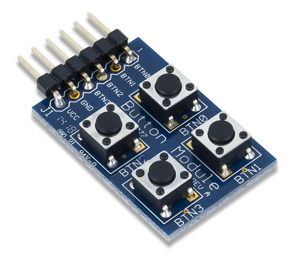
PMOD Button:
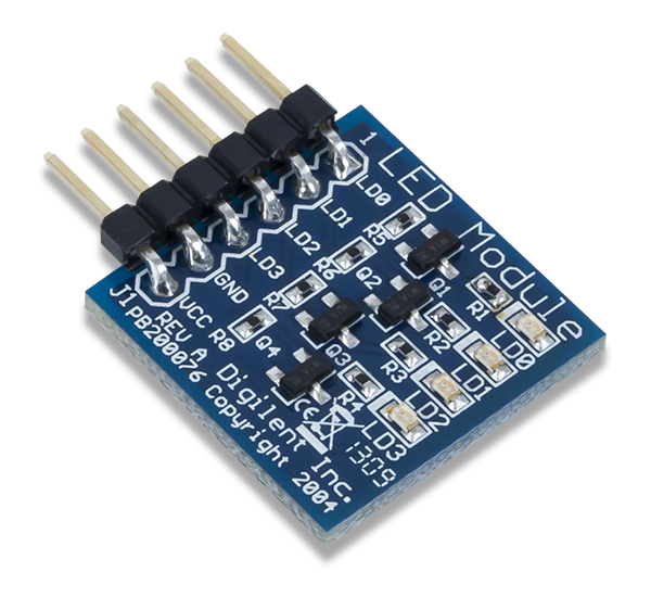
PMOD Led :
Clone and build the below Github repository:
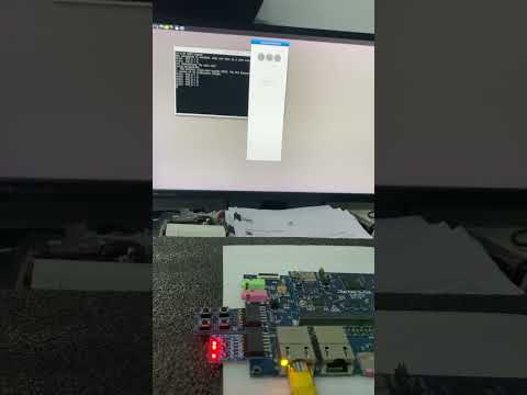
For the matching to the configurations in our software program, plug the PMOD board to Renesas RZ/G2L. Connect the Led board to the lower pins of PMOD0 on Renesas carrier board, and connect the button board to the lower pins of PMOD1.

Transfer the executable q563_rzgpio to Renesas RZ/G2L, then run it,
./q563_rzgpio
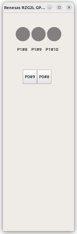
This is a two-way test, click the button on the screen will see the on/off of Led, click on the PMOD buttons will see the color change of the red light on screen.